Views: 0 Author: Site Editor Publish Time: 2026-11-02 Origin: Site


Trusting an invisible force to suspend heavy steel loads creates intense operational anxiety. Buyers naturally doubt a purely magnetic grip. Watching massive payloads dangle mid-air triggers genuine workplace safety concerns. Unsafe lifting practices directly cause catastrophic facility accidents. Poor rigging methods lead to severe compliance violations. Equipment drops guarantee massive production downtime and physical injuries. We must establish a scientifically accurate baseline. A permanent magnetic lifter remains exceptionally safe. This safety applies strictly when operators respect its physical limitations. Teams must mathematically verify safety margins before executing every single lift. Facilities also need to intensely train workers on their specific deployment environments. Understanding the core physics eliminates these perceived operational risks entirely. You will soon discover how these devices secure heavy payloads reliably. We will explore the specific environmental variables threatening their grip. Finally, you will learn exactly how international regulators evaluate lifting safety.
Fail-Safe Design: Permanent magnetic lifters do not require electricity; they cannot drop loads due to facility power failures.
Safety Ratios are Mandatory: Industry-compliant lifters are rated with a 3:1 or 2:1 safety factor (Working Load Limit) to account for real-world variables.
Grip is Conditional: A lifter’s rated capacity assumes flat, clean, thick, low-carbon steel. Paint, rust, air gaps, and thin materials drastically reduce hold strength.
Human Factor: The majority of magnetic lifting failures stem from operator error (misjudging the center of gravity or ignoring surface conditions) rather than equipment failure.
Many operators view industrial magnets as mysterious black boxes. In reality, they operate on highly predictable, basic physics. You can calculate their exact holding force prior to lifting. We must examine the mechanical components creating this invisible strength.
A standard unit contains extraordinarily powerful neodymium magnets. These internal components generate a constant, powerful flux field. A diametrically magnetized cylinder sits inside the main steel housing. You activate the device by rotating an external lever. Turning this handle rotates the internal magnetic cylinder. The internal magnetic poles align perfectly when fully engaged. The flux field then pushes aggressively downward. It penetrates deeply into the steel load below. You simply rotate the handle back to release the load. This physical action short-circuits the magnetic field entirely. The flux remains trapped safely inside the upper steel housing. The load immediately drops away from the contact face.
A widespread industry misconception involves electrical grid dependency. Older electromagnet systems required constant, uninterrupted electricity to function. Electromagnets dropped their loads instantly if facility power failed. Permanent units eliminate this massive hazard completely. They operate entirely independently of the local electrical grid. A facility power outage has zero effect on holding strength. The internal neodymium magnets provide all the necessary lifting energy. This fail-safe design guarantees the load remains suspended safely during blackouts. Operators never need to fear sudden electrical infrastructure failures.
Physical security mechanisms prevent catastrophic mid-air releases. You cannot simply bump the handle to release a payload. Industry-grade handles feature a robust, spring-loaded safety latch. This latch locks the lever securely in the active position. Accidental bumps cannot disengage the device. Harsh vibrations during overhead transit will not move the handle. Swinging motions cannot defeat the primary locking pin. The operator must manually pull a physical pin backward. Only then can they rotate the lever to demagnetize the system. This mandatory two-step process eliminates accidental load drops.
A maximum magnet rating usually assumes perfect laboratory conditions. Real-world industrial applications rarely provide these ideal scenarios. You must understand exactly how environmental variables degrade holding power. Ignoring these factors compromises facility safety immediately.
Magnets require a specific volume of metal to function optimally. The payload steel must absorb the full magnetic flux. Thin materials simply cannot absorb all the generated energy. Excess magnetic field spills out into the surrounding air. Engineers call this phenomenon a lack of magnetic saturation. Thin sheets lower the effective holding force dramatically. Every device features a specific mathematical tear-off point. This point defines when the magnet overpowers the material's structural capacity. The payload peels away easily if the metal is too thin. You must always consult the manufacturer’s thickness derating charts.
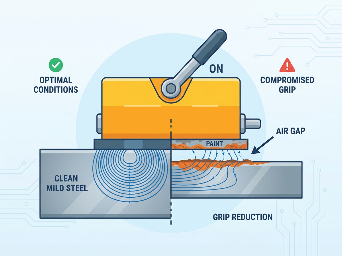
Magnetic flux severely struggles to travel through empty air. The strongest hold requires direct, flush metal-to-metal contact. Rough surface finishes ruin this perfect physical connection immediately. Heavy rust creates microscopic air gaps across the surface. Thick mill scale acts exactly like a physical barrier. A reality check becomes absolutely necessary here. Even a tiny 0.5mm air gap compromises safety severely. Such a small gap reduces total lifting capacity by up to 50%. Operators must aggressively clean and inspect the contact surface before lifting.
Different steel alloys absorb magnetic flux at completely different rates. Low-carbon steel acts as the perfect magnetic conductor. It easily yields 100% of the device's rated lifting capacity. High-carbon steels restrict the internal flow of magnetic energy. Cast iron presents significant safety challenges for lifting crews. Cast iron contains graphite flakes and higher carbon levels. Lifting cast iron components reduces total capacity by roughly 50%. You must actively derate your equipment based on the exact alloy.
Estimated Capacity Derating by Material Type
Material Type | Magnetic Saturation Quality | Estimated Lifting Capacity |
|---|---|---|
Low-Carbon Steel (Mild Steel) | Excellent | 100% of Rated Capacity |
High-Carbon Steel | Moderate | 70% - 80% of Rated Capacity |
Cast Iron | Poor | 50% - 65% of Rated Capacity |
Alloy Steel (e.g., 300 Series Stainless) | Non-Magnetic / Very Poor | 0% - 10% (Unsafe for lifting) |
Heavy industry tolerates absolutely zero guesswork regarding overhead lifting. Safety authorities heavily regulate all close-proximity lifting devices globally. Regulators strictly enforce compliance to prevent fatal workplace accidents. You must understand the specific rules governing your equipment.
The American Society of Mechanical Engineers publishes extremely rigorous guidelines. ASME B30.20 governs below-the-hook lifting devices specifically. It outlines strict structural and testing requirements for all manufacturers. The standard dictates how internal components must endure mechanical stress. It mandates thorough visual inspections before every daily shift. Manufacturers must permanently affix physical identification tags displaying the rated load. Compliance ensures the device handles intense industrial repetition safely over time. Facilities failing to meet ASME standards face immediate operational shutdowns.
Global safety authorities share a remarkably unified stance on overhead lifting. The UK’s Health and Safety Executive (HSE) enforces uncompromising lifting legislation. The Lifting Operations and Lifting Equipment Regulations (LOLER) classify magnets strictly. HSE requires thorough, documented examinations of all active lifting accessories. Safety inspectors actively look for structural fatigue and damaged handles. They check for missing safety latches and illegible capacity tags. International bodies expect regular, certified testing to verify ongoing performance. Proper documentation proves you maintain a compliant, safe working environment.
A safety factor provides a crucial mathematical buffer for operations. A 3:1 Working Load Limit (WLL) indicates a massive safety margin. Suppose a unit has a safe working rating of 1,000 kg. It actually requires 3,000 kg of pull force to tear off. This baseline testing occurs under completely ideal, flat steel conditions. This 3:1 ratio absorbs the violent shock of sudden crane movements. It helps mitigate minor surface impurities safely during a lift. Some standards allow a 2:1 safety factor for highly controlled environments. You must strongly avoid non-certified imported units lacking proper documentation. Unverified imports often claim high capacities without genuine tear-off testing.
Even perfectly manufactured tools fail rapidly under poor human operation. Application realities require vigilant oversight from floor managers. Operators must recognize when environmental factors make lifting inherently unsafe. Training remains your primary defense against catastrophic equipment failures.
Incorrect load placement remains a major daily operational hazard. The magnet must sit directly over the payload's precise center of gravity. The load will tilt violently when lifted if placed off-center. This unexpected tilting action creates a highly dangerous peel effect. The peel effect pries the load away from the magnet face. A peeling force requires significantly less energy to detach a load. It defeats the magnet much faster than a straight vertical pull. Operators must carefully find the balance point before hoisting heavy beams.
Extreme ambient heat permanently damages internal magnetic structures. Standard neodymium magnets lose structural strength at high temperatures. Performance drops noticeably when ambient temperatures exceed 80°C (176°F). Exposure to temperatures beyond 150°C can demagnetize the unit entirely. Foundries and heavy forging plants present severe thermal risks to equipment. High-temperature environments require highly specialized lifting devices. These high-temp models utilize completely different magnetic alloys like Samarium Cobalt. Always verify the maximum operating temperature before deploying any unit.
Lifting large, thin steel sheets poses a unique mechanical threat. A single central magnet creates extreme overhangs on wide plates. The edges of the thin sheet will sag downward due to gravity. This physical sagging causes the material to flex intensely. The flexing action literally peels the sheet away from the magnet face. We strongly advise against using a single unit for large sheets. You should deploy customized spreader beams instead. Spreader beams suspend multiple magnets evenly across the entire sheet length. This distributes the weight properly and prevents dangerous material sag.
Selecting the right tool requires methodical, evidence-based evaluation. You cannot rely on marketing brochures or maximum capacity claims alone. Operational safety depends on proven testing and appropriate mechanical design. Follow a strict shortlisting process to protect your workers.
Never accept generalized batch approximations from any equipment supplier. Insist on rigorous documentation proving individual unit testing. A reputable manufacturer provides a unique testing certificate for every serial number. This certificate must display the exact tear-off force achieved during testing. It proves the specific unit meets the required 3:1 safety factor. If a vendor cannot produce this individual report, walk away immediately.
The activation handle acts as the primary safety interface for operators. Look for highly ergonomic designs protecting the operator's hands from pinching. The locking mechanism must feature a high-tension physical safety latch. It should actively resist accidental disengagement during violent transit movements. Test the handle manually to ensure the locking pin engages deeply. Flimsy latches pose a severe, unacceptable risk to floor personnel.
Many facilities frequently lift cylindrical loads like pipes or round bars. A completely flat bottom cannot safely secure a round payload. Verify the unit features a deeply machined V-shoe design underneath. The V-groove provides two distinct longitudinal lines of magnetic contact. You must accurately calculate the derated capacity for all round materials. Cylindrical shapes often reduce the effective holding capacity by up to 50%. The vendor must supply a specific derating chart for round loads.
A mismatch between device size and payload size causes instant instability. Ensure the contact area matches your specific daily material dimensions. We recommend following a strict evaluation checklist:
Review the specific tear-off certification for the exact serial number you intend to purchase.
Inspect the physical safety latch to guarantee spring tension remains firm and responsive.
Calculate the required V-groove derating if your daily operations involve pipes or round bar stock.
Measure your typical payload dimensions to match the exact surface footprint of the magnetic shoe.
A footprint too large for the payload wastes valuable magnetic flux. A footprint too small concentrates too much physical stress on a tiny surface. Analyze your most common steel dimensions before approving any purchase.
We can confidently classify magnetic lifters as highly reliable industrial tools. They utilize mathematically predictable forces to secure tremendous weights safely. Following core safety variables ensures entirely incident-free daily operations. You must always account for material thickness, surface air gaps, and load balance. We strongly recommend prioritizing vendors offering full testing transparency. Seek out suppliers providing detailed capacity-derating charts and verified tear-off certificates. Do not compromise on structural quality when lives depend on a secure hold. Finally, implement comprehensive, mandatory operator training guidelines across your entire facility. Educated operators represent your absolute strongest defense against workplace lifting hazards.
A: They lose magnetism extremely slowly, typically less than 1% per decade. You will not notice any performance drop during normal operations. Loss only occurs if exposed to extreme ambient heat or severe physical trauma. Always keep the unit away from open flames, welding arcs, or high-impact collisions to preserve the internal neodymium field.
A: Paint acts exactly like an air gap. It physically separates the magnet face from the conductive steel. Operators must consult the manufacturer's specific air gap derating curve before lifting. This crucial chart helps determine the true safe working load based on the exact paint thickness. Thick industrial coatings drastically reduce safe holding power.
A: While they don't require "calibration" like a digital scale, they do need thorough attention. They strictly require annual recertification and tear-off testing. This rigorous testing ensures they continue to comply with local and international lifting safety regulations. Routine testing confirms the 3:1 safety factor remains structurally intact after a year of heavy use.