Views: 0 Author: Site Editor Publish Time: 2026-09-23 Origin: Site


In continuous casting, controlling the flow of molten steel is the defining factor between a high-grade product and expensive scrap. Metallurgists know uneven solidification ruins steel quality. While adding a continuous casting electromagnetic stirrer improves fluid dynamics, installing it in the wrong zone yields marginal returns. It often fails to solve specific metallurgical defects. You cannot simply clamp a coil onto a strand and expect perfection.
The strategic selection of electromagnetic stirrer position directly dictates which quality metrics you optimize. Whether you place it in the mold, the strand, or the final solidification zone matters immensely. Each zone handles different stages of cooling. By selecting the correct location, you take control over surface finish, internal porosity, and centerline segregation. Read on to learn how to match your caster’s unique geometry and defect history to the ideal stirring setup.
To understand why placement dictates success, you must first look at the physics of stirring. The process relies on Lorentz forces. When you apply a low-frequency alternating magnetic field to the caster, it penetrates the copper mold or the solidified steel shell. It induces eddy currents inside the highly conductive liquid steel. The interaction between the magnetic field and these currents generates Lorentz forces. These forces drive the molten steel into controlled rotational or linear motion. You create an artificial washing effect. This movement alters temperature gradients and physically sweeps away trapped non-metallic inclusions.
However, fluid dynamics vary drastically from the meniscus down to the unsolidified core. A continuous casting electromagnetic stirrer acts differently depending on the solid fraction of the steel it targets. At the meniscus, the steel is almost entirely liquid. Flow control here is highly responsive. Deep within the metallurgical length, the steel transforms into a viscous, mushy slurry. Moving this high-solid-fraction material requires vastly different magnetic penetration and power levels.
Because of this phase change, you must map your common casting defects to specific solidification zones. Pinholes and slag entrapment originate at the meniscus. V-segregation and central porosity occur during the final stages of core solidification. By matching the electromagnetic stirrer position to the origin point of your worst defects, you strike at the root cause rather than treating symptoms.
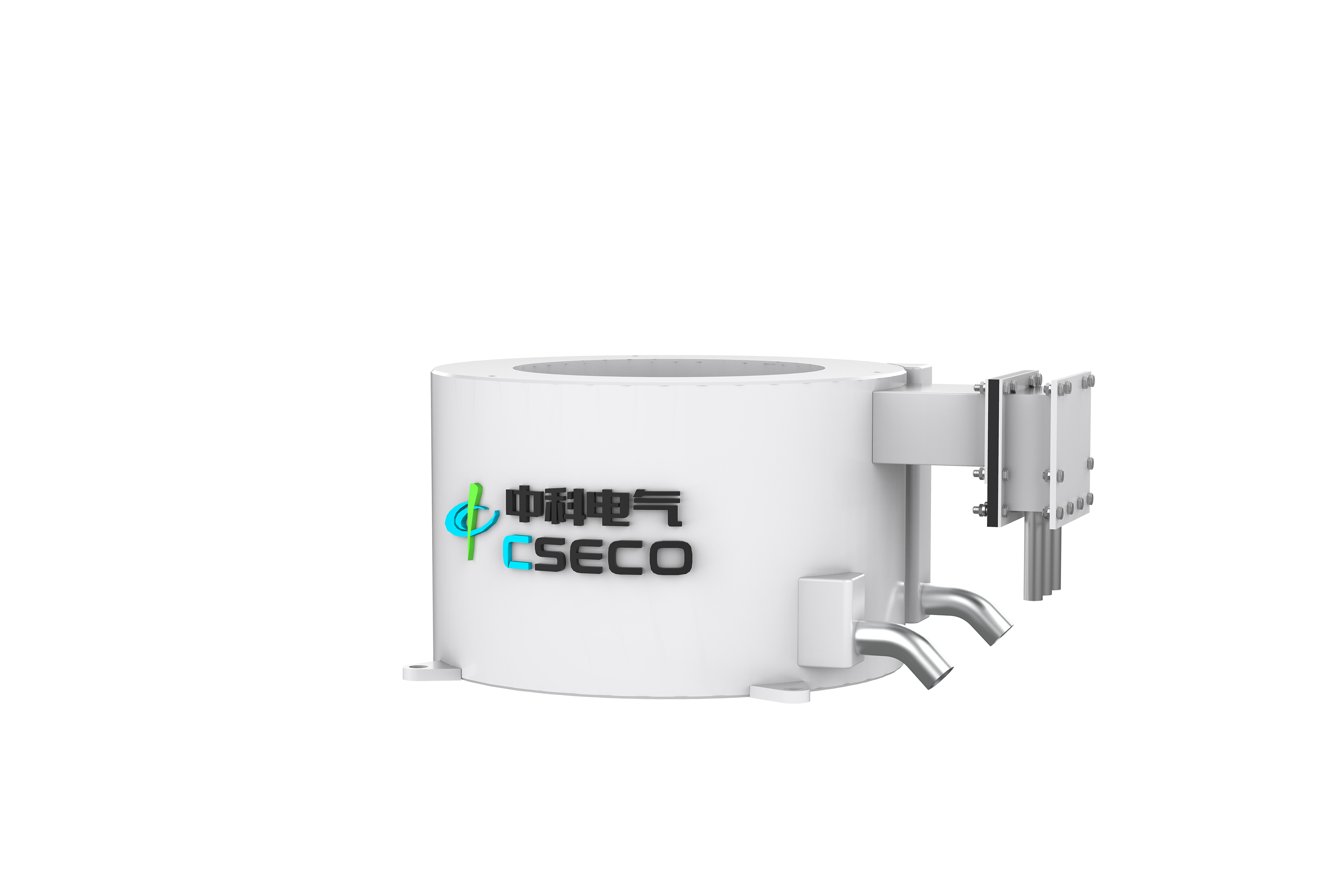
The mold electromagnetic stirrer (M-EMS) serves as the first line of defense for steel quality. We install it directly around the mold copper tube or within the mold housing. Its primary job is to control the liquid steel flow at the meniscus and manage the initial solidification shell.
When you activate an M-EMS, it rapidly accelerates the fluid in a horizontal, swirling motion. This specific electromagnetic stirrer position delivers several critical primary quality outcomes:
From an evaluation standpoint, M-EMS is strictly required for certain operational profiles. It is best for steel plants struggling with surface cracking or severe slag entrapment. Furthermore, if you produce strict surface-quality grades, this setup is non-negotiable. Automotive exposed panels, high-carbon wire rods, and seamless pipe grades demand pristine sub-surface conditions. A mold stirrer ensures the outer shell forms flawlessly before the strand enters the secondary cooling zone.
While M-EMS perfects the surface, internal structural integrity requires intervention further down the caster. This is where strand and final stirrers come into play. They tackle the complex defects born deep inside the solidifying core.
The evaluation criteria for these lower zones depend entirely on product dimensions and steel grades. S-EMS and F-EMS setups are mandatory for thick slabs, heavy blooms, and large billets. For high-carbon steels, bearing steels, and specialized alloys, internal soundness dictates final product viability. Without controlling the core structure, these grades will inevitably fail during downstream rolling or forging.
Selecting the optimal electromagnetic stirrer position requires a systematic approach. You cannot guess where to place the magnetic coils. You must let your defect history and geometric constraints drive the engineering decision.
Your defect history should immediately narrow down your options. If your primary rejections stem from surface defects, you must prioritize M-EMS. If ultrasonic testing reveals poor internal structure or severe chemical segregation, prioritize S-EMS or F-EMS. For high-alloy or specialty steel production, a single unit rarely suffices. Metallurgists often require a combined approach, such as M-EMS plus F-EMS, to secure both the shell and the core.
Section size also dictates technical feasibility. Geometries fundamentally alter magnetic field penetration requirements. Billets are relatively small. A standard rotary stirrer easily penetrates the entire cross-section. Slabs, however, are wide and thick. They require massive, straight-sided coils producing traveling wave magnetic fields. Blooms sit somewhere in the middle. You must match the physical coil design to the strand dimensions to ensure the Lorentz forces actually reach the liquid core.
Below is a quick reference framework to help categorize your operational needs.
| Primary Defect Type | Solidification Origin Zone | Recommended Stirrer Setup | Expected Metallurgical Outcome |
|---|---|---|---|
| Pinholes, Slag Entrapment | Meniscus / Initial Shell | M-EMS (Mold) | Clean sub-surface, uniform initial shell growth. |
| Internal Cracks, Columnar Growth | Secondary Cooling Zone | S-EMS (Strand) | Maximized equiaxed crystal zone, reduced cracking. |
| Centerline Segregation, Porosity | Crater End / Final Core | F-EMS (Final) | Dense core structure, minimized carbon segregation. |
| Combined Surface & Core Defects | Meniscus + Crater End | M-EMS + F-EMS | Comprehensive quality control for alloy/bearing steels. |
Finally, establish strict performance metrics before procurement. You need a baseline. Define success criteria like a specific percentage increase in the equiaxed zone area. You might also track the reduction in the carbon segregation index. By setting these benchmarks, you can accurately validate the investment post-installation.
The theoretical benefits of stirring are undeniable. Yet, the physical installation introduces significant engineering hurdles. Space and geometry constraints usually pose the biggest threat to successful deployment. An S-EMS requires careful integration around existing support rolls. If the roll pitch is too tight, you may need custom flat stirrers. Similarly, an M-EMS must fit within your existing mold housing parameters. Modifying copper water jackets to accommodate bulky coils is both difficult and expensive.
Plant managers must also weigh power consumption against yield gains. Running high-frequency or low-frequency magnetic fields requires substantial electrical OPEX. You need specialized transformers and frequency converters. You must calculate the cost of this continuous electrical draw against the financial benefit of reducing scrapped or downgraded steel. In most high-grade steel applications, the yield gain easily covers the OPEX, but the math must be verified.
Cooling and maintenance demand equal attention. Coils operate inches away from glowing, liquid steel. They require internal water-cooling systems utilizing highly purified water. Address the realities of maintaining these systems in harsh, high-temperature caster environments. If a cooling loop clogs or fails, the electromagnetic coils will overheat and short circuit almost immediately.
Because physical modifications are costly, simulation verification is critical. Emphasize the necessity of using MHD (Magnetohydrodynamic) computational modeling. You must couple MHD software with CFD (Computational Fluid Dynamics) tools. This allows you to simulate fluid flows and magnetic penetration before you cut any steel. Validating the chosen electromagnetic stirrer position digitally eliminates the risk of an ineffective installation.
The correct electromagnetic stirrer position is a precision tool, not a blanket fix. Position directly dictates metallurgical performance. You must deploy stirring energy exactly where the physical state of the steel can benefit from it most. Washing the meniscus prevents surface flaws, while shearing the mushy zone prevents core voids.
Base your procurement decisions on hard data. Analyze your metallurgical defect history to pinpoint the origin of your quality issues. Audit your caster for space availability. Above all, demand computational fluid dynamics simulations from your equipment vendors before finalizing the design.
Stop accepting downgraded heats as a normal cost of doing business. Schedule a comprehensive metallurgical assessment of your caster today. Request an engineering feasibility study to discover precisely which stirring configuration will elevate your continuous casting line.
A: Yes. Multi-stirring combinations (such as M-EMS + S-EMS or M-EMS + F-EMS) are standard industry practice. They are highly recommended for high-grade alloy and large bloom casting. Using multiple units allows you to control both surface finish and internal core quality simultaneously throughout the entire cooling process.
A: It requires an engineering audit of the roll pitch in your secondary cooling zone. Standard cylindrical stirrers require significant clearance. However, if space is highly restricted, vendors can design custom flat stirrers or specialized compact units to safely bypass tight structural clearances.
A: Yes. Position directly dictates power needs. M-EMS generally operates at different frequencies than S-EMS or F-EMS. The magnetic field must penetrate different thicknesses of copper molds, support rolls, and solidifying steel shells. Deeper penetration into high-solid-fraction steel requires lower frequencies and substantially higher power inputs.